Overview
A Flow is the Designer Element visually represents the logic used to execute a process. Flows can move and manipulate data, perform various actions, and provide functionality to other Designer Elements. These processes are created by adding and configuring functions referred to as Steps. Steps are a graphic way to represent each point within a Flow. Steps are added to Flows via the Flow Designer from the step catalog known as the Toolbox. The following article will walk through the basics of creating a Flow.
Example
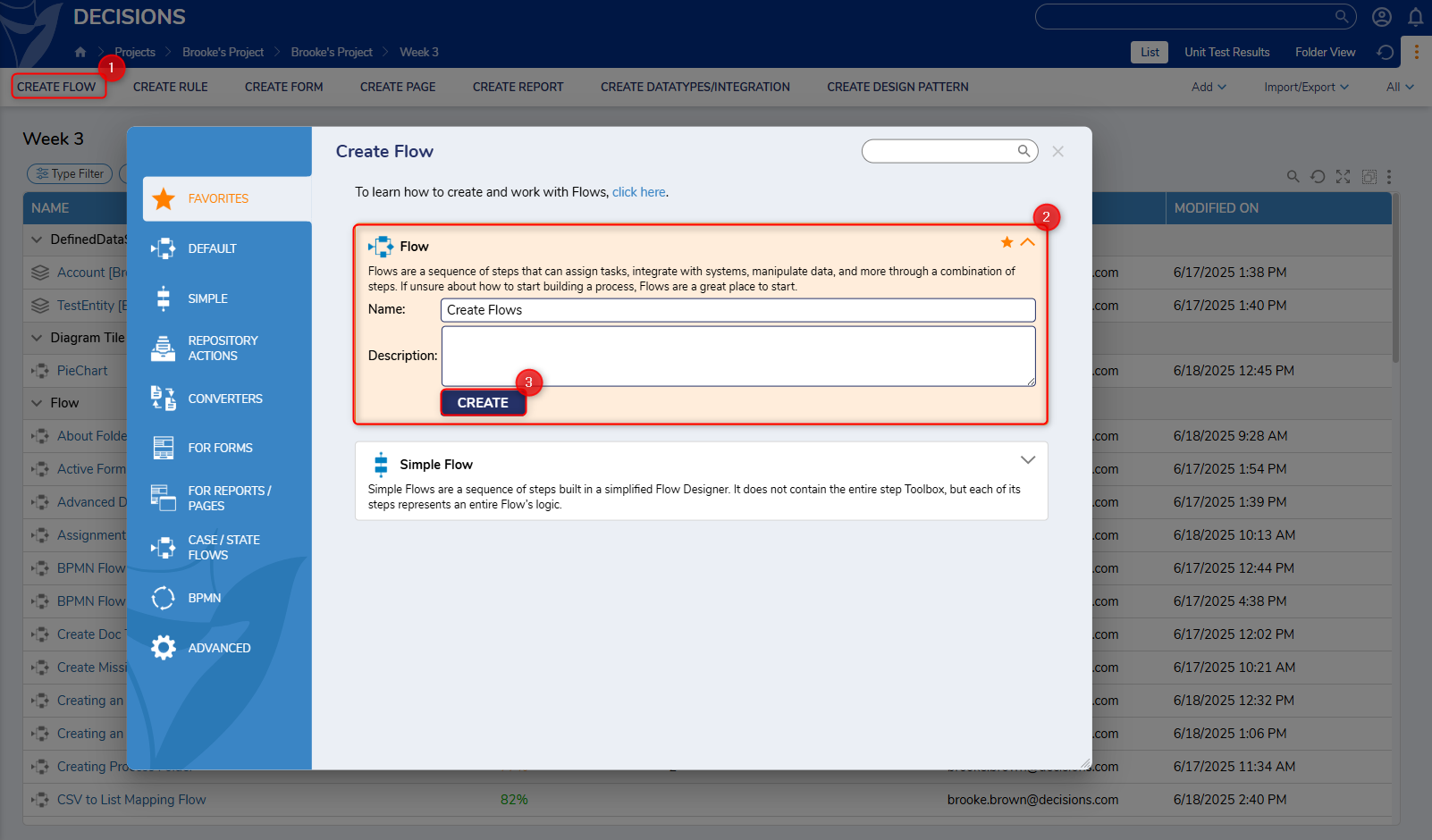
- In a Designer Project, select CREATE FLOW.
- The Create Flow gallery will appear, displaying various Flow Behavior options. Select Flow found under the Favorites or Default sections.
- Enter a Flow name in the text box provided. Select CREATE.
 Once the Flow has been created, selecting the Info in the side panel can provide the user with various details of the Flow, such as the name, Owner, and Flow ID.
Option Description View History Views the history of the Flow. Name The provided Name for the Flow. This field can be updated with the changes reflected in the portal after the Flow is saved. Description A written description of the Flow. Owner The current owner of the Flow. Based on specific designer settings, the owner can be notified if changes are made to the Flow. The Current owner can be updated using the Pick action. Tags Tags can be added to the Flow for easier searchability in the portal. Behavior Name The current Flow behavior used by the Flow. Element Attribute Provides information on the current Designer Element to which this item belongs. Created in Version The version the Flow was initially built in. Modified in Version The version the Flow was last updated in. Id The Flow ID is used for identifying the Flow in the database. ID's of Designer Elements can also be found in the URL while in the editor or within the Data Explorer. Created On Date The date the Flow was built. Modified Date The latest date the Flow was saved and changed. Created By The account associated with making the Flow. Modified By The account that had most recently modified the Flow. 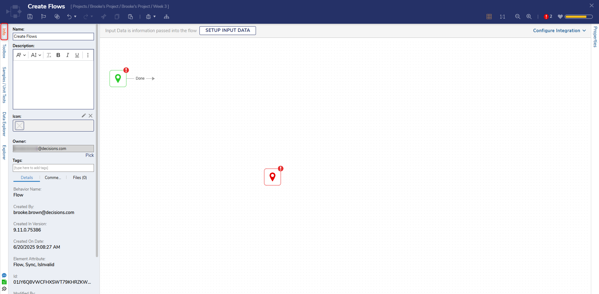
- At the top of the Flow Designer, select SETUP INPUT DATA. Input Data is data passed into the Flow to manipulate with Steps.
- In the Flow Input Data dialog, select DEFINE under Define Input Data to open the [Flow Name]: Input Data window.
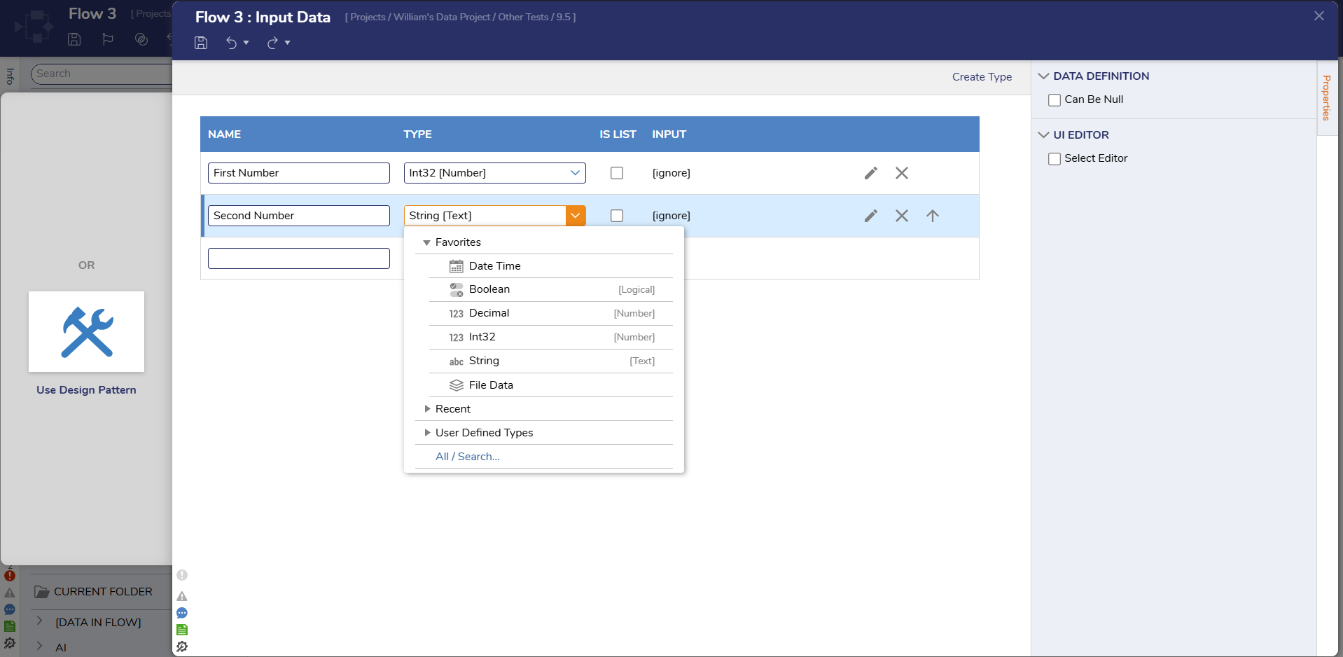
The Input Data window is where data that needs to pass through the Flow can be defined. This window presents three fields that can be configured for each piece of data; Name,Type, and Is List. Alternative to the Input Data window, data can also be defined in the Properties panel of the Start step.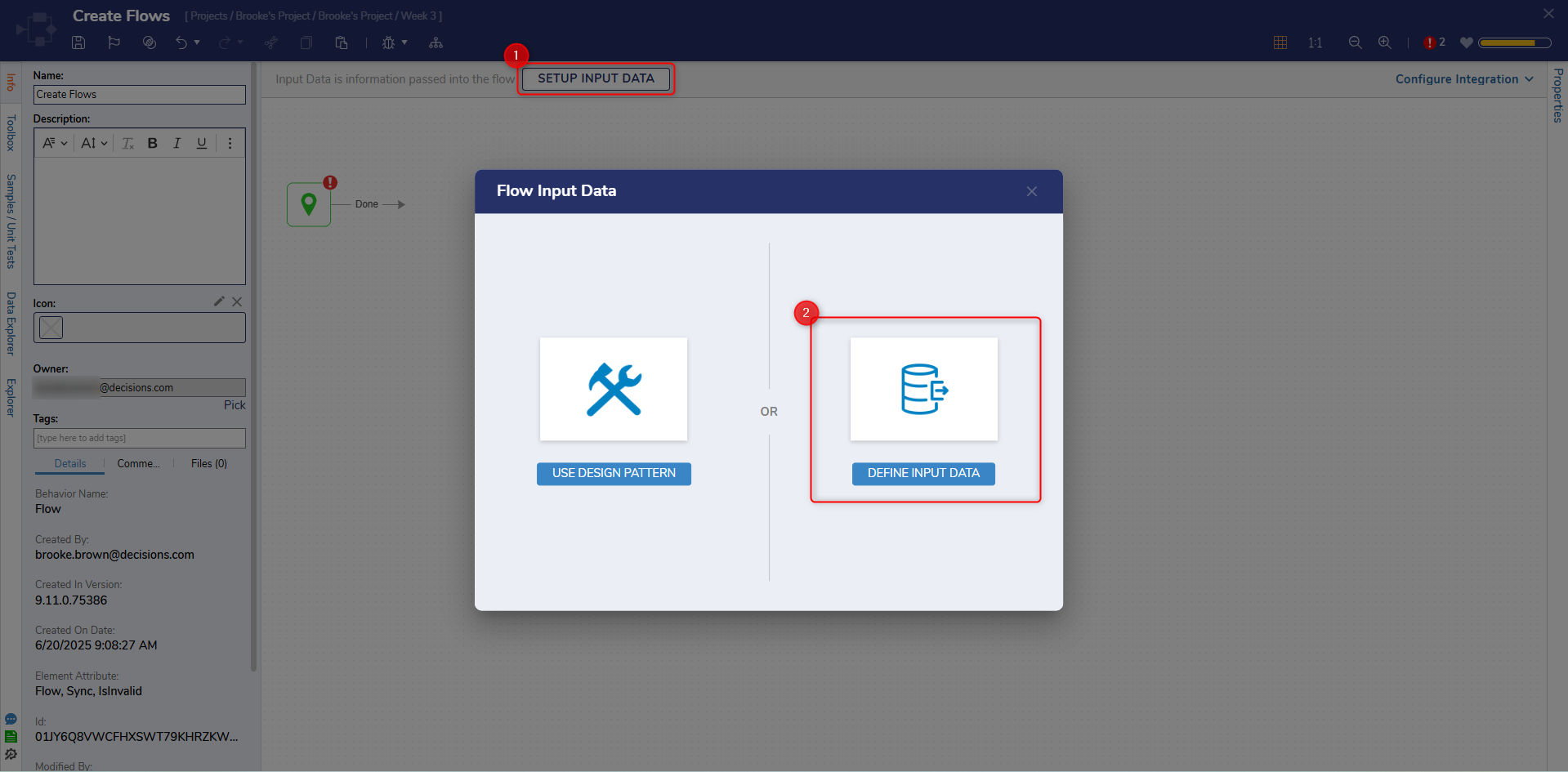
- In the [Flow Name]: Input Data window, type "First Number" in the Name field on the first line. Expand the drop-down list for Type and select Int32 [Number]. Leave the 'Is List' option unchecked.
- On the second line, type "Second Number" for the Name, select Int32[Number] for the Type, and leave Is List unchecked.
- Select Save and then close the Input Data window.
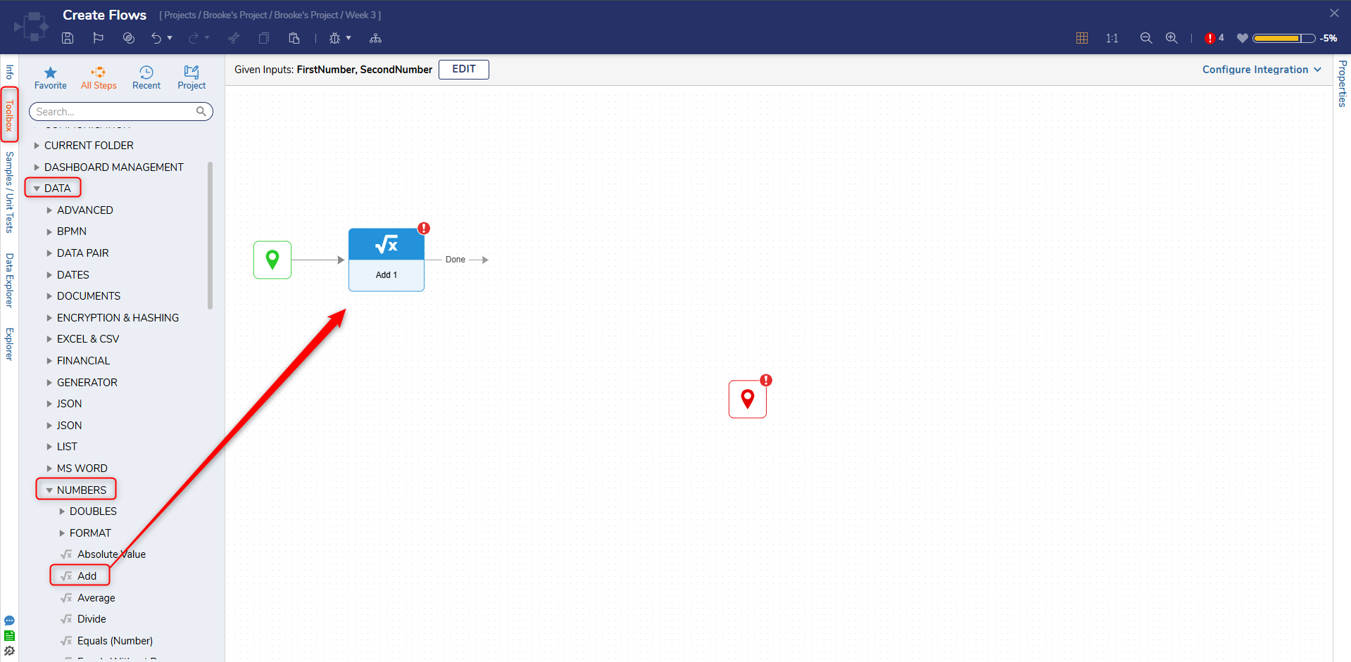
- In the Toolbox panel, expand DATA > NUMBERS. Drag and drop the Add step onto the workspace. Connect the Start step to the Add step. The Toolbox houses thousands of Steps that manipulate and move data throughout a Flow.
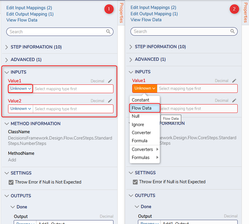
- With the Add step selected, navigate to the Properties panel.
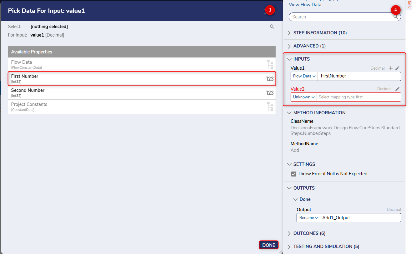
The step Properties panel includes step settings, additional outcome paths, testing and simulation settings, and inputs and outputs. Input is the expected data that the step needs to function. Next to each input is a drop-down list set to Unknown by default. This drop-down represents the Mapping Type for an input value. Output is the information the step passes out once it has finished its process.In the Help Center section of the Flow, a red exclamation mark will appear when new steps are added that have not been configured yet. This indicates an Exception within the Flow that would need to be resolved before the Flow can function as intended. - Under Inputs > Value1 select Pick. In the Pick Data For Input: value1 dialog, choose First Number.
- Under Inputs > Value2 select Pick. In the Pick Data For Input: value2 dialog, choose Second Number. Alternatively, begin typing "Second Number" within the textbox to display a drop-down of all matching data available to the Flow.
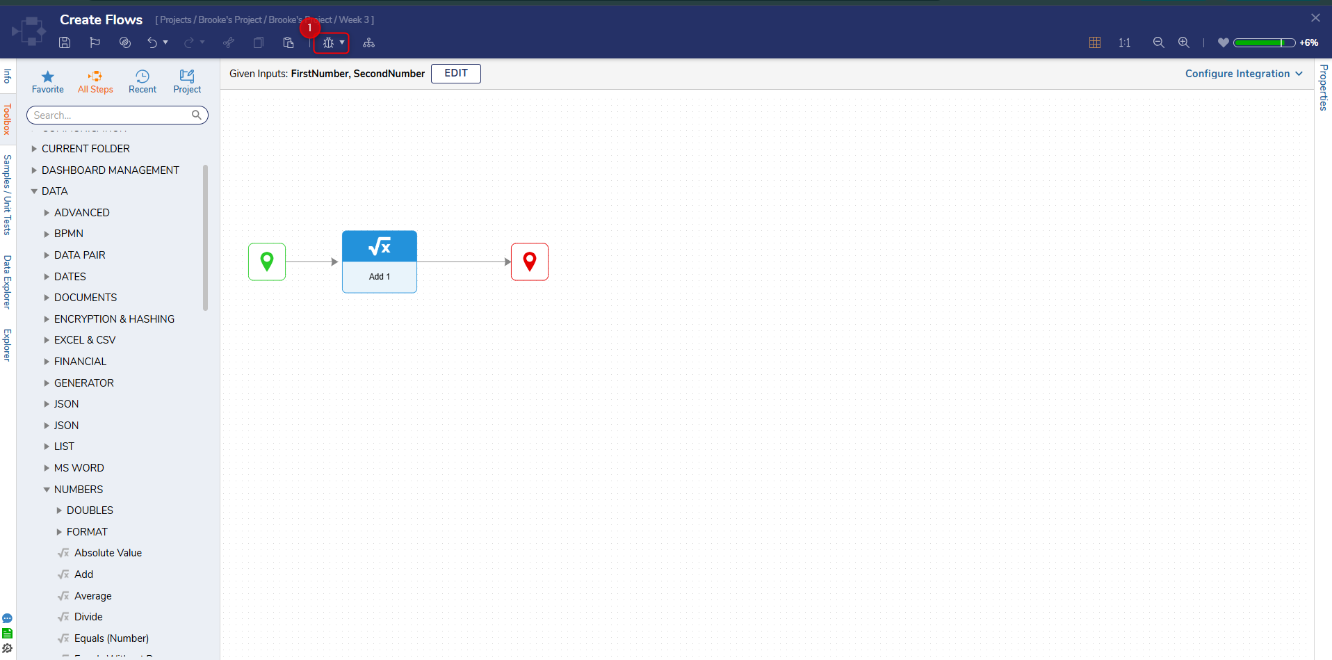
- Connect the outcome path from the Add step to the End step. Move the End step next to the other logic; it is best practice to keep lines within the Flow straight to have an organized view.
- Select Debug in the top action bar.
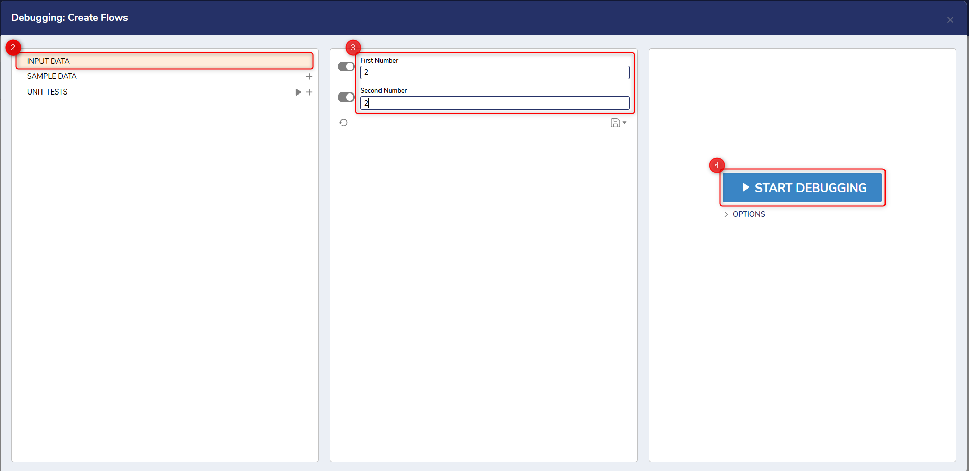
The Debugger is a tool that tests the Flow to confirm that the logic is working as expected. It will show the number of times a step was reached, its path, and input and output data to see how it changes from step to step. - Type numbers into the First and Second Number boxes and select Start Debugging.
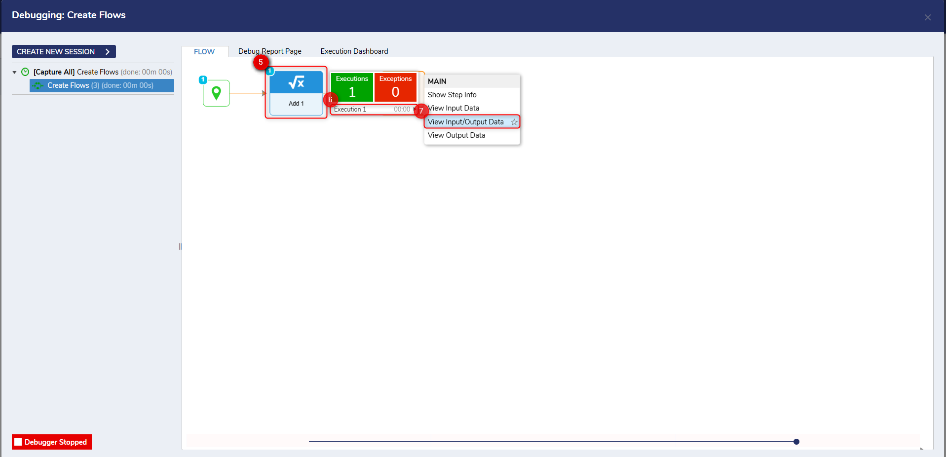
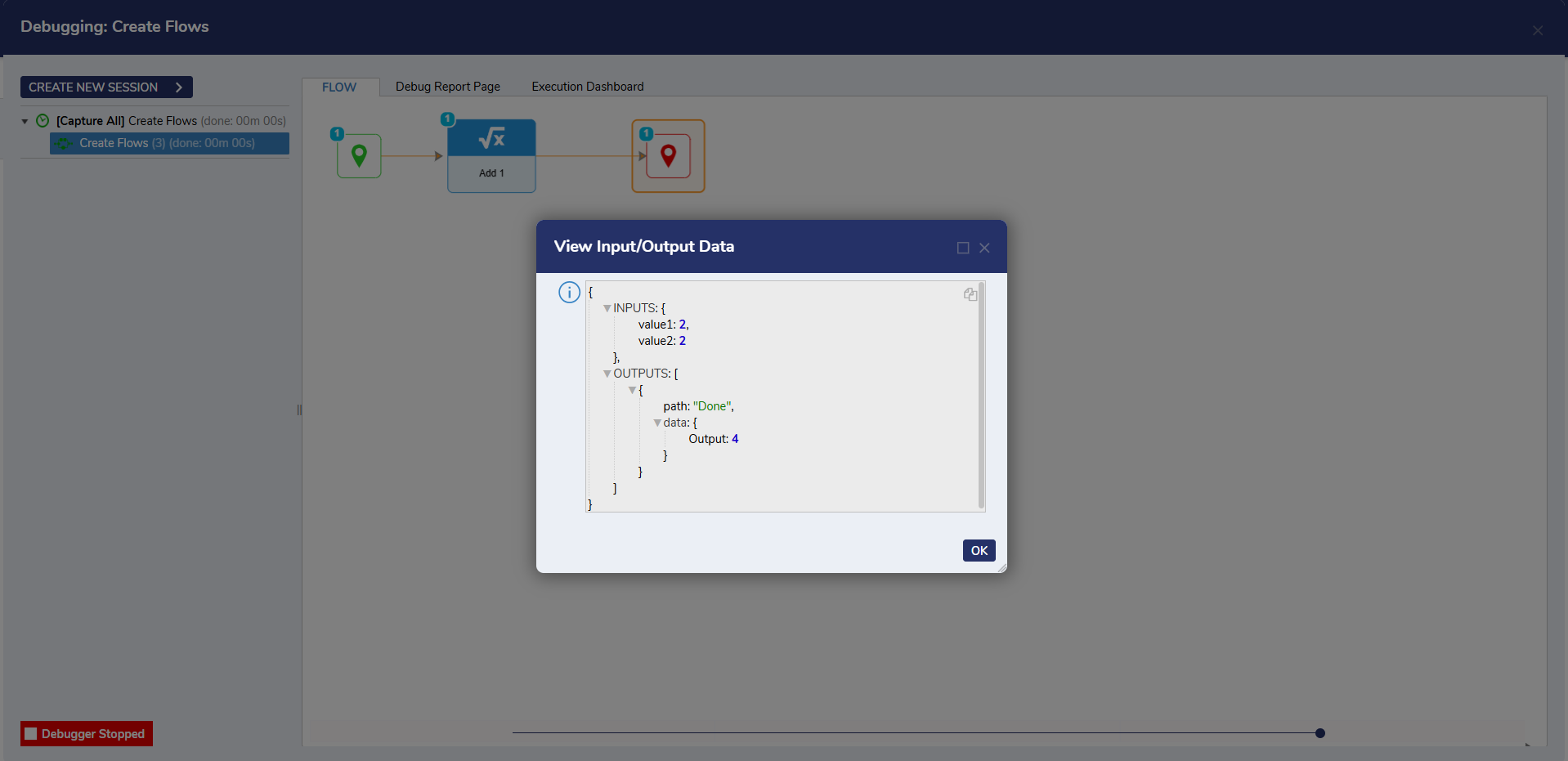
- In the Debugger, right-click the Add step, then select View Input/Output Data to display the numbers that the step added and the result.
Reviewing Mappings in the Data Explorer
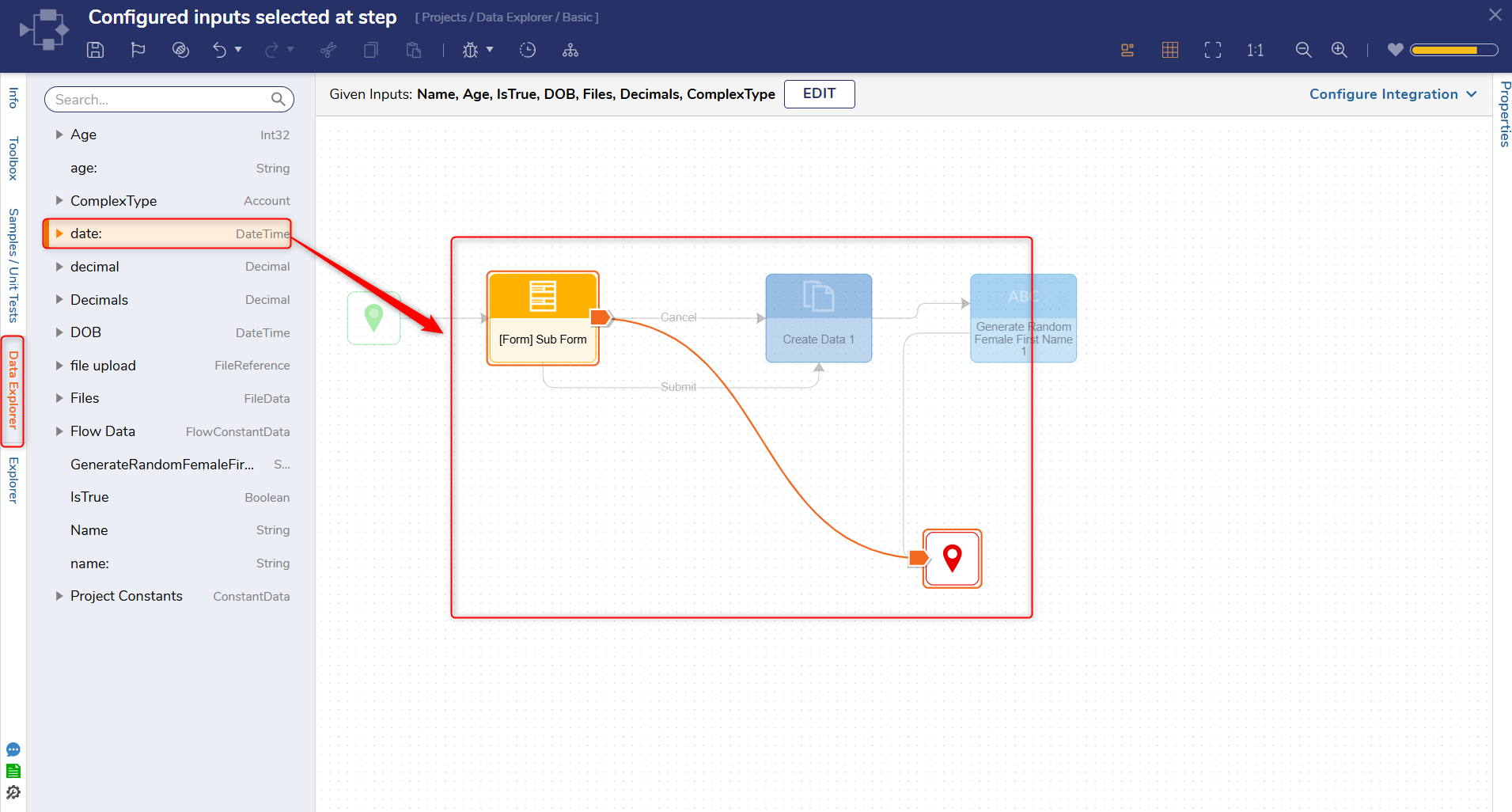
After the Flow is configured, the Data Explorer can be used to review mapped data within the Flow Designer. Selecting an input from the Explorer tree displays arrows to indicate its mapping. Steps associated with the selected input are emphasized, while the remaining steps are minimized.
Feature Changes
| Description | Version | Release | Developer Task |
|---|---|---|---|
| The Data Explorer has been enhanced to display arrows for mapped inputs and emphasize the corresponding steps while minimizing the remaining steps. | 9.21 | March 2026 | [DT-046504] |
| The Type Picker has been redesigned. This can be found when selecting Edit Input Data and then picking the data type. | 9.5 | November 2024 | [DT-042365] |