Overview
BPMN (or Business Process Modeling Notation) is a standard notation system that is used to graphically represent business processes. Through the use of implementations in installations v.6/v.7, users are provided the ability to create Flows using BPMN steps in the Step Catalog. Additionally, if desired, users may also Upload preexisting BPMN XML files into Decisions, for conversion into a Flow. This allows users the ability to use BPMN as a base for laying out projects within the Flow engine. The following document demonstrates how to create a BPMN-based Flow in the Flow Designer.
BPMN Steps
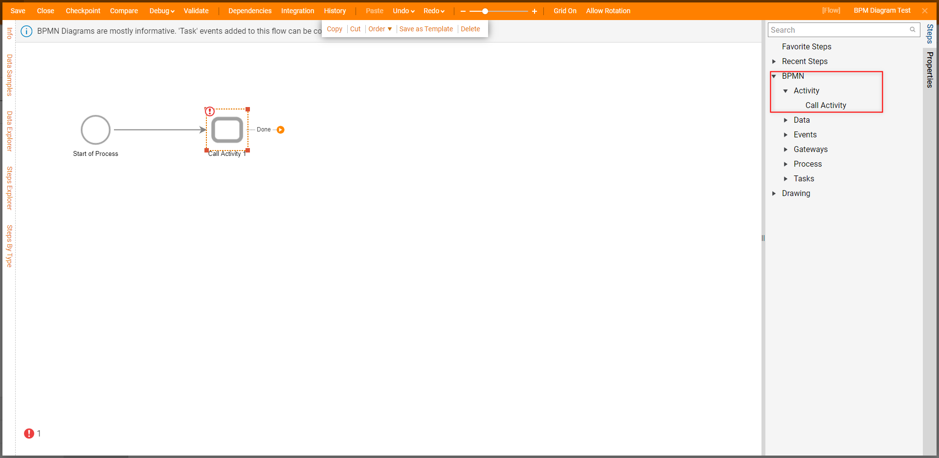
BPMN steps can be found by creating a new Flow, and selecting BPMN Diagram, or by navigating to Steps > BPMN from the Flow Designer. This category allows users to access additional categories to provide further customization of their BPMN Flow.
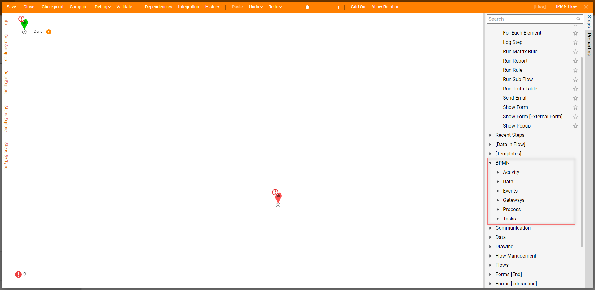
The categories and their functions are as follows:
| Category | Description |
|---|---|
| Activity | Provides step to Call Activity which provides a method for performing an action. |
| Data | Offers steps that deal with Data handling. This includes Input, Output, creating a Data Object, or storing Data. |
| Events | Provides steps pertaining to major points ("Events") in a Process. |
| Gateways | Steps that allow the Designer to split the Path of the Flow/BPMN Diagram. |
| Process | Provides a step for running Sub-Processes (similar to Sub Flow functionality). |
| Tasks | Provides steps relating to specific tasks. |
Example
To create a Flow using BPMN steps:
- Navigate to a Designer Project in Decisions Studio, select CREATE FLOW from the Global Action Bar. Navigate to Flow [BPMN], then select and create a BPMN Diagram.
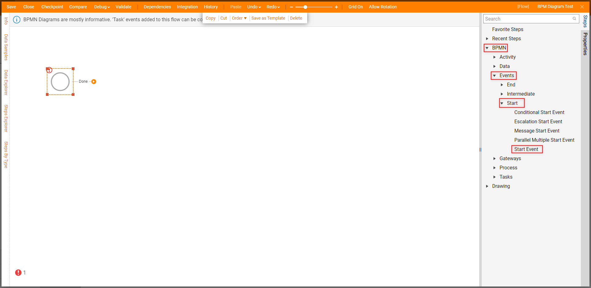
- From the Flow Designer, navigate to Steps > BPMN > Start, and drag a Start Event step into the workspace.
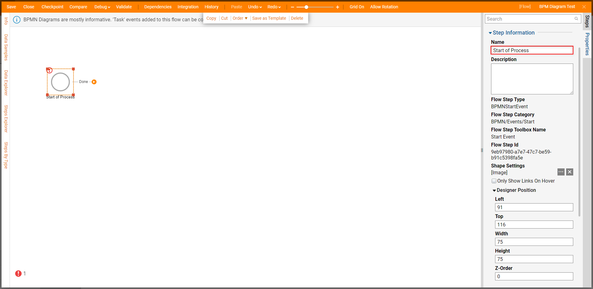
- Navigate to Properties > Step Information, and provide the desire Name value for the Start Event.
- From Steps > BPMN > Activity, attach a Call Activity step to the Done path of the Start Event step.
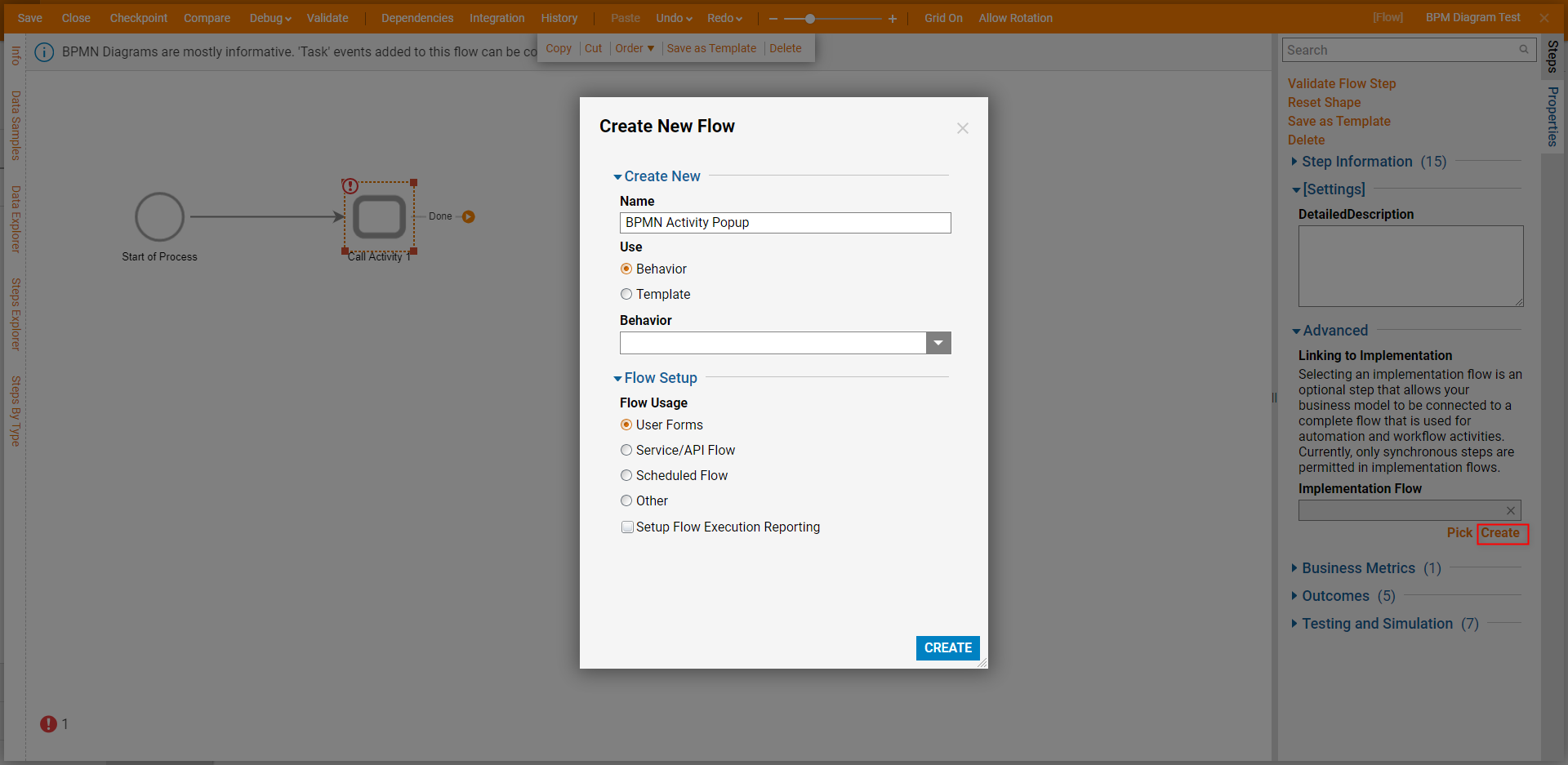
- From the Properties tab of the Call Activity step, navigate to Advanced > Implementation Flow, then Create a new Flow. Additional Information on Implementation Flows.Implementation Flows are used to connect a BPMN Flow to an external Flow to accomplish a section of the modeled Business Process.
From the Flow Designer, design the Flow as desired, then Save, and Close.
Example Flow ConfigFor this example, attach a Show Popup step from the Favorite Steps category to the Start and End steps. From the step's Properties, Constant map the desired Subject and Message value.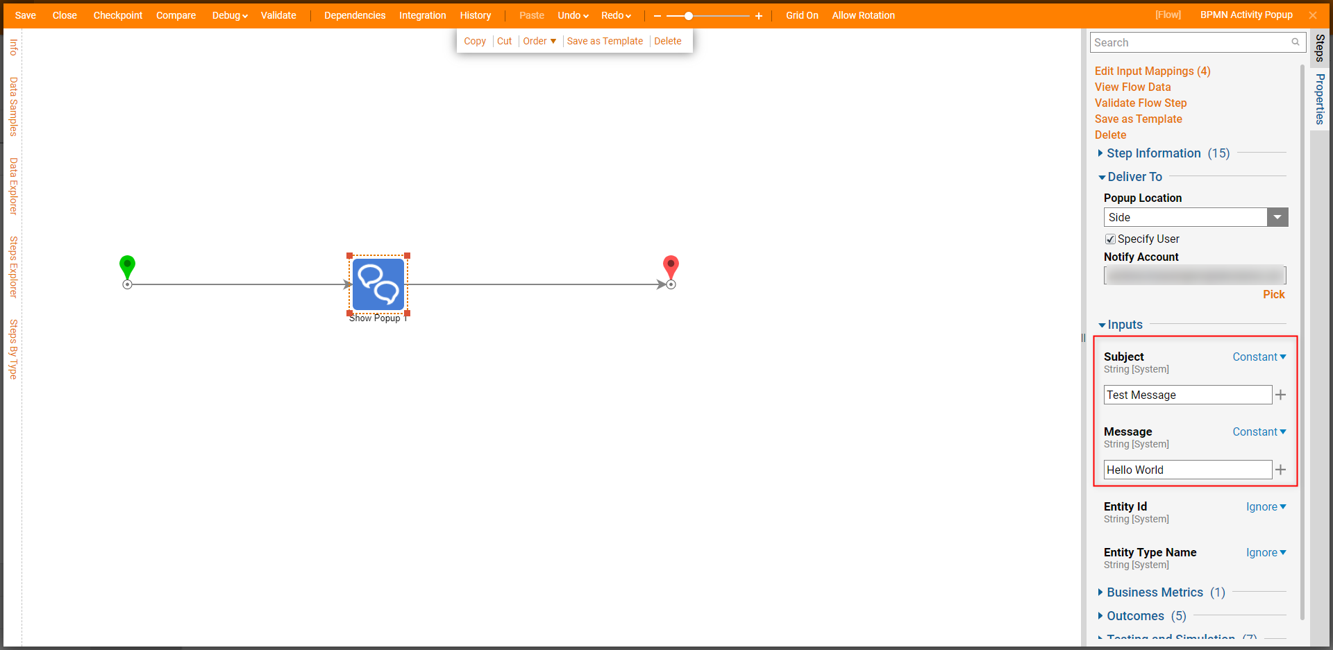
Back in the BPMN Flow's Flow Designer, connect an End Event step from Steps > BPMN > Events > End to the Call Activity step; redefine the step's Name if desired.
Note on Start/End EventStart Event and End Event function similarly to a standard Start/End step in that they begin or end the Process respectively, and can be used to define Input/Output data.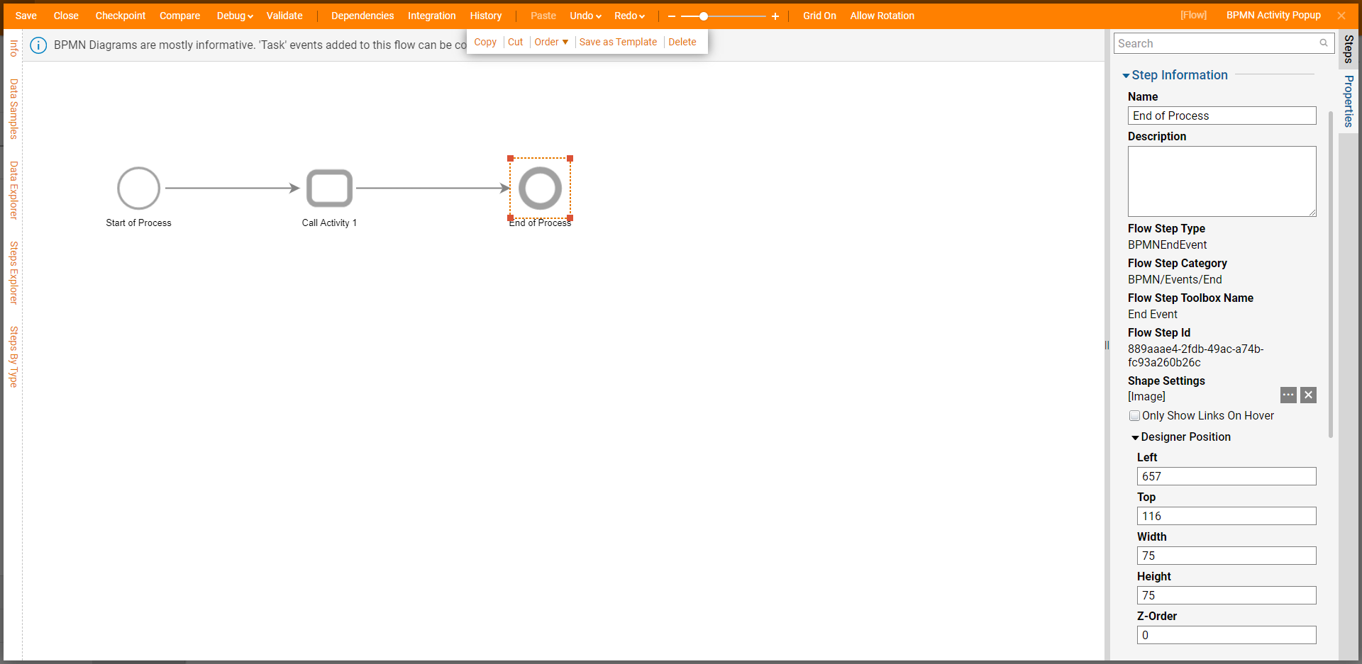
Save the Flow, then if desired Close the Flow.
Debug
- From the top Action bar in the Flow Designer, select Debug. Then click FULL.
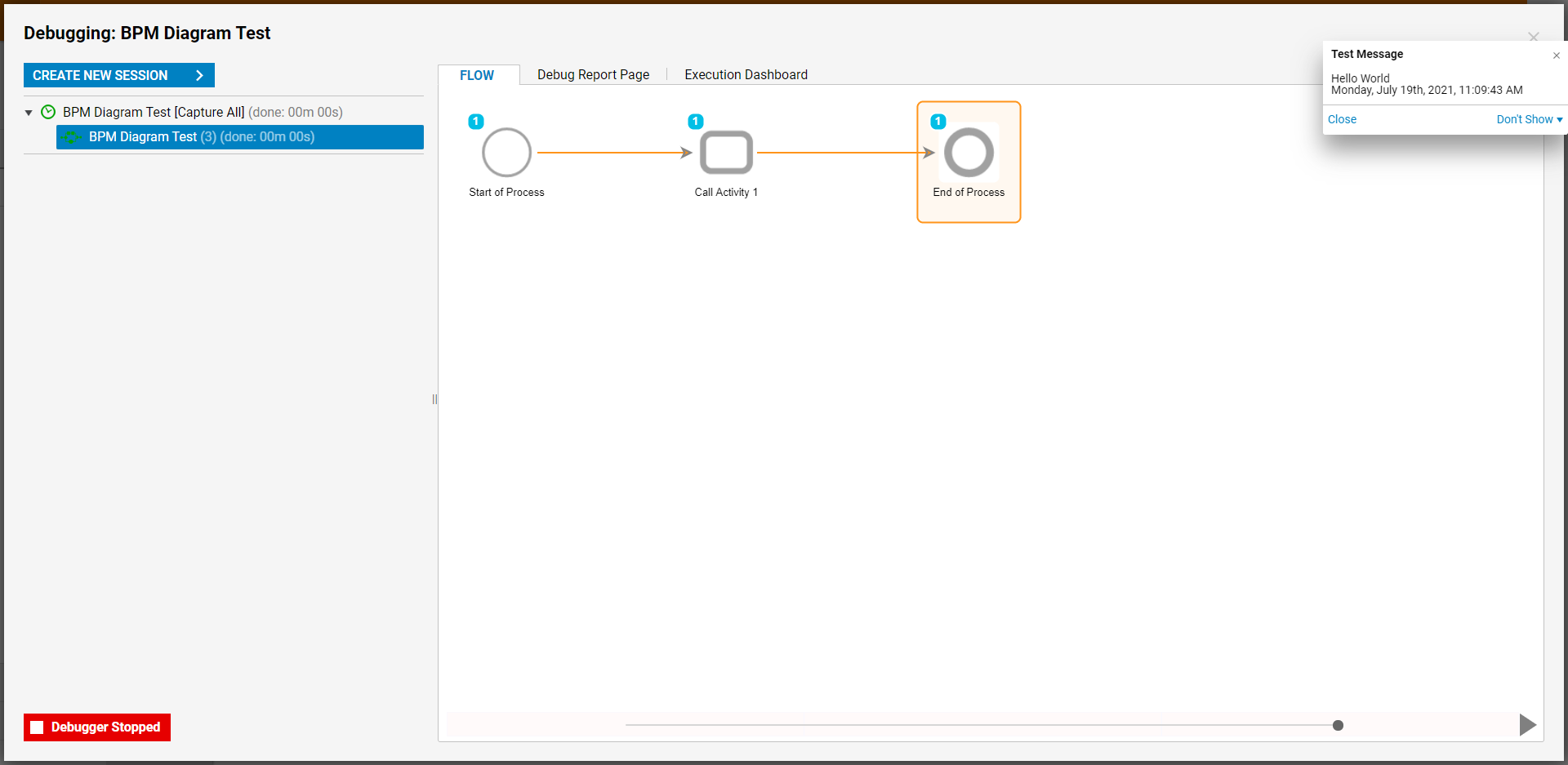
- Verify that the Flow passes through the complete BPMN Diagram and that the Popup displays as expected.
